| Shourt Line by Soft Works Ltd. | |||||
|
Model Railroad Products
|
|||||
Power Supply Connector Assembly Instructions
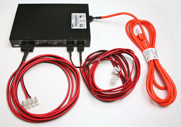
| Overview: The SL-PS800-3-28 DC Regulated Switching Power Supply comes with all connectors but not cables. Assembled cables are available on the product page - click here to view. The end user can assemble the connectors to cables of their choice by following these directions.
Tools Required: The following tools are required
Materials Required:
|
||||||
|
|
||||||
| Procedure for assembling an AC power cable: | ||||||
 |
||||||
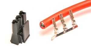
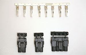
| Step 1: Read all the steps below before proceeding then:
Locate the 3 connectors and connector housing that came with the Power Supply |
||||||
 |
||||||
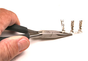
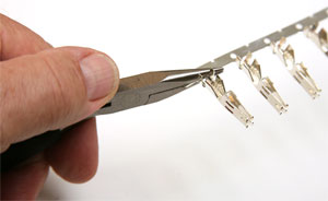
| Step 2: Separate the three connectors from the carrier strip by holding with pliers and moving the connectors back and forth until they break off the carrier | ||||||
 |
||||||
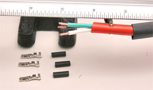
| Step 3: Remove 1.25" of insulation from cable and strip each wire .25". Cut 3 ea. .5" lengths of heat shrink tubing to fit over each wire. Cut 1.5" length of heat shrink tubing to fit over cable diameter. | ||||||
 |
||||||
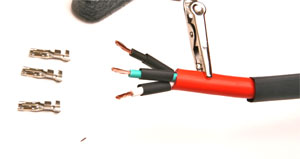
| Step 4: Fit heat shrink over each wire and cable | ||||||
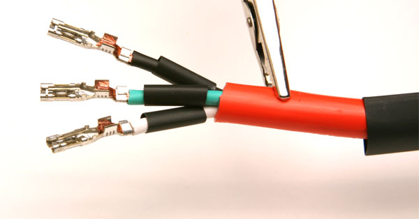
| Step 5: Crimp the tabs of each connector over wire by using a small needle nose pliers to fold each side, one side at a time over the wire as shown below | ||||||
 |
||||||
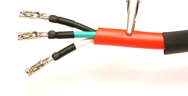
| Step 6: Crimp upper tabs over each wire, move heat shrink up to cover lower crimped tabs and then solder upper crimp by adding solder to bare copper wire, the heat shrink tubing will shrink from the heat of soldering as shown below | ||||||
 |
||||||
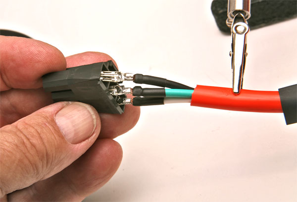
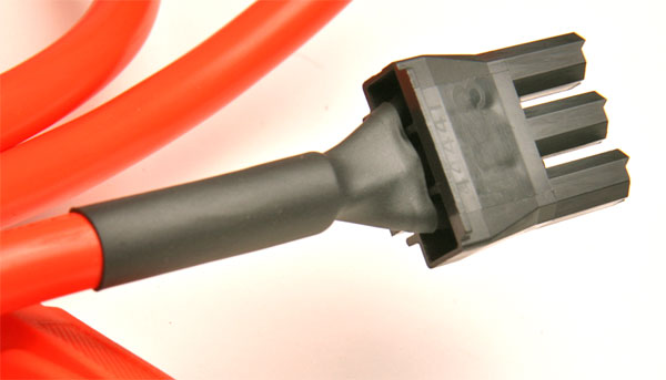
| Step 7: Insert all there connectors into housing at the same time. Note that the connectors are at an right angle to the housing as shown below. Insert each wire until each connector snaps and locks into the housing. | ||||||
 |
||||||
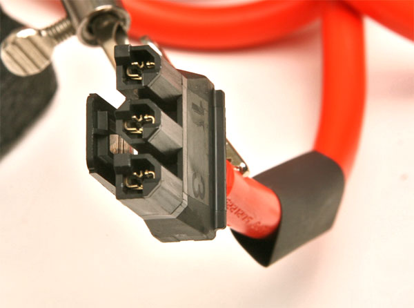
| Step 8: Notice the orientation of each connector in the plug housing as shown below. Note that the black wire (hot) goes into housing slot #1, green (ground) wire into the center, and white (neutral) wire into housing slot #3. | ||||||
 |
||||||
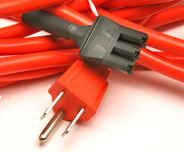
| Step 9: Move cable heat shrink up to connector housing and shrink with heat gun. The finished connector show look like the one below | ||||||
 |
||||||
| Step 10: Finished cable | ||||||
 |
||||||
|
|
||||||
| Procedure for assembling an 10 awg DC power cable: | ||||||
| Step 1: Read all the steps below before proceeding then:
Locate the 4 connectors and DC 4 connector housing that came with the Power Supply . Note that each connector has locking tab attached that easily comes loose from the connector. These keep the metal plugs in place inside the connector housing. Remove the tap from the 4 connector housing. |
 |
|||||
 |
||||||
| Step 2: Separate the four connectors from the carrier strip (that has 8 attached) by holding with pliers and moving the connectors back and forth until they break off the carrier | ||||||
| Step 3: Use 10 gauge wire for the 20 amp output of the supply. Locate all items shown before continuing. Use either one or two cables depending upon your distribution needs. | 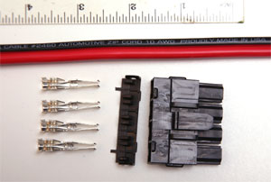 |
|||||
| Step 4: Cut 1 ea. .5" lengths of heat shrink tubing to fit over each wire. Cut 1.5" length of heat shrink tubing to fit over cable diameter. Use either one or two cables depending upon your distribution needs. | 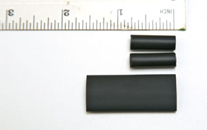 |
|||||
| Step 5: Fit heat shrink over each wire and cable | 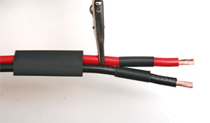 |
|||||
| Step 6: Crimp the tabs of each connector over wire by using a small needle nose pliers to fold each side, one side at a time over the wire as shown below | 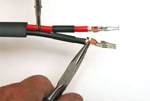 |
|||||
| Step 7: Crimp upper tabs over each wire, move heat shrink up to cover lower crimped tabs and then solder upper crimp by adding solder to bare copper wire, the heat shrink tubing will shrink from the heat of soldering as shown. | 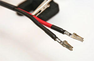 |
|||||
| Step 7: Insert all wires into connector housing at the same time. Note that the latch of the housing is facing down (with the locking holes showing on top of the housing) and that the red wire is on the left side (positive wire). Insert each wire until each connector is about 1/8 inch from the other side of the housing. | 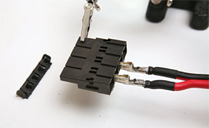 |
|||||
| Step 8a: Place keeping tab into the holes on top of the housing and lock the tabs onto the side of the connector housing. DO NOT FORCE the tab. | 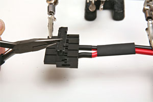 |
|||||
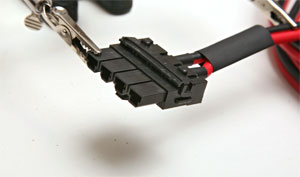
| Step 8b: If the keeping tab does not snap into place, like the one in the picture on the right, continue with the next step, otherwise continue on step 9 below.
Note that the locking tab in the photo does not sit flat on the connector housing, but that the side tabs are locked. This will not hold the wires in place and must be fixed in step 8c below. |
 |
|||||
| Step 8c: Use a screwdriver to carefully release the sides of the locking tab and then remove the locking tab. | 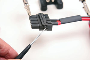 |
|||||
| Step 8d: Use a screwdriver to carefully push the plastic parts inside each hole toward the center of the connector by gently twisting the screwdriver until the hole is clear enough to accept the locking tab. Go back to step 8a above. | 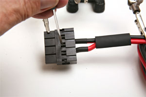 |
|||||
| Step 9: Use a heat gun to shrink the cable heat shrink tubing on the finished connector. | 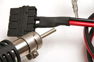 |
|||||
| Step 9: Connect a terminal block on the other end of the cable for easy connection to DCC systems or DC throttles. Plug into the transformer in port A and test. | 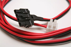 |
|||||
| Finished cables with the 30 amp 4 plug connector with only one cable used for power. An additional cable can be added later to this connector inserting the provided metal connectors into the unused slots in the housing. | ||||||
 |
||||||