| Shourt Line by Soft Works Ltd. | |||||
Model Railroad Products |
|||||
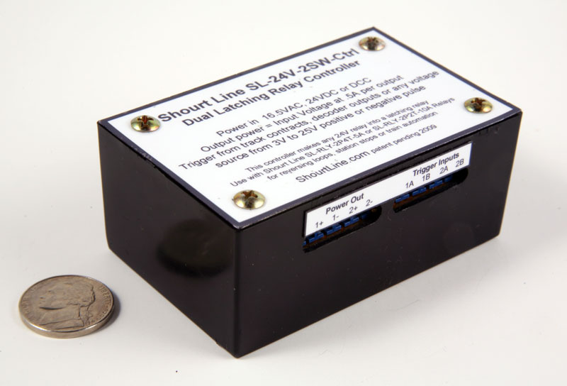
SL-24V-2SW-Ctrl Dual Latching Relay Controller New Product
Makes any relay a latching relay for train and signal automation
Use with Shourt Line SL-RLY-2P4T-5A or SL-RLY-2P2T-10A Relays for reversing loops, station stops, train synchronization and train automation
When used with two SL-RLY-2P4T- 5A relays it is a replacement for and functionally identical to the electrical switching abilities of two EPL switch motors with auxiliary switches but with 2X more switch contacts and expanded logic abilities.
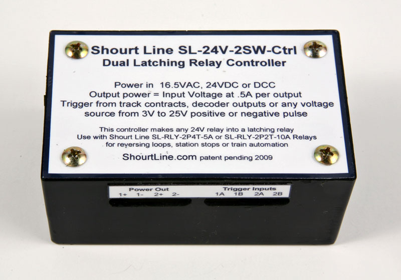
Runs on DC, DCC, MTS, or AC power and triggers with any track contacts or AC or DC positive or negative pulses
Price: $49.95 New
Features:
- Operating voltage 12 to 18 Volts AC, 18 to 24 Volts DC, DCC or MTS
- Built in power supply for operation from AC power sources
- 2 Trigger inputs for each channel
- Trigger on Positive, Negative or Ground Voltage using DC or AC current
- Output current .5 amp per channel
- Easy to hook-up using only a screw driver
- Use with or without external relays for switching on and off any type of DC or AC load
- Safe for continuous use (loco parked over track contact switch)
Specifications:
Mfg: Made in the USA by the Shourt Line - Soft Works Ltd.
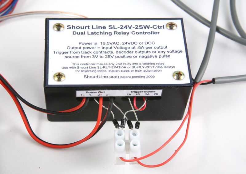
Components: High Voltage (50V) Integrated Circuit with open collector outputs and low voltage low current trigger inputs
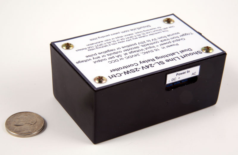
Power In Terminals: < 10ma of current to operate with outputs off
AC: 24 Volts Max. DC or 18V Max. AC, DCC or MTS (Shourt Line SL-PS-16AC40 16 VAC 40 Watt Transformer recommended)
DC: Input 24 Volts Max. DC (Also provides DC voltage output when power in input on AC terminals)
Power Out Terminals: Outputs 1 and 2 can each drive a 1/2 amp load like a relay or EPL switch motor. (see How to Use details below for more information on how to use the outputs)
1+:.Positive Voltage DC output (same as DC+ terminal on Power In terminal)
1-:.Negative Voltage DC output switched to ground when input is triggered ON
2+:.Positive Voltage DC output (same as DC+ terminal on Power In terminal)
2-:.Negative Voltage DC output switched to ground when input is triggered ON
Output - terminals are open collector and can switch any load to ground up to 50VDC at 1/2 amp continuous.
Output - terminals are reverse diode protected to suppress back EMF voltage when an inductive load like a relay is switched off. This prevents noise feeding back to other devices or the power supply..
Trigger Input Terminals: The trigger inputs, A and B for each output, will turn the respective output ON or OFF depend on the polarity of the signal and which terminal is triggered. Trigger Input pulses are referenced to DC - terminal which is at ground potential. (see How to Use details below for more information on how to use the outputs)
1A:.Positive Pulse will turn the Output 1 ON - Negative or Ground Pulse will turn the Output 1 OFF
1B:.Positive Pulse will turn the Output 1 OFF - Negative Ground Pulse will turn the Output 1 ON
2A:.Positive Pulse will turn the Output 2 ON - Negative or Ground Pulse will turn the Output 2 OFF
2B:.Positive Pulse will turn the Output 2 OFF - Negative or Ground Pulse will turn the Output 2 ONTrigger Pulses -are referenced to DC - terminal which is at ground potential.
Tract Contacts- with or without diodes can be used for triggering by connecting between the DC+ terminal either the A or B terminal to force the output ON and OFF respectively.
Tract Contacts- with diodes that are connect to an AC power source can also be used for triggering by connecting between the DC - terminal (which must also be connected to AC power common lead) and either the A terminal to force the output ON and OFF when a positive or negative pulse is applied respectively.
Maximum Ambient Operating Temperature: 200 degrees Fahrenheit ( 93 Celsius)
Weight: 4 Oz.
Dimensions: 2.7"L X 1.7"W " X1.2"H
Photos:
Applications:
This controller has two independent latching circuits that can be used to drive lights, motors and relays from very low voltage, low current sources such as track contacts, switch boxes, photo electric and IR sensors and many other devices. The flexible logic inputs allows both simple and complex applications.
Typical applications include:
- Trolley Line Reversal end of line and stops at stations
- Reversing loop control
- Stop on DC DCC/MTS train automation with deceleration, stopping, starting and acceleration
- Station Stops, Starts and Slow Speed Controls
- Signal Controls
- Train Automation
- Animation Displays
- Sharing Common track between two types of track power manually or via automation
- Synchronize two or more trains running on the same track so they have constant separation
- Automate Two trains on one track with two sources of power and independent direction and speed.
- All types of EPL switch and train control previously done with LGB controllers and diode logic
- Many other types of layout controls and automation
How to use the SL-24V-2SW-Ctrl to run two trains on the same track with separate power, speed and direction controls:
SL-24V-2SW-Ctrl can be used to automate two trains on the same track when used with two SL-TC-17100-nt Track Contacts and Two SL-RLY-2P4T-5A-24VDC Relays. The following application demonstrates how to run two trains from independent train power sources (DC, DCC, AC or any two) in any direction and speed while sharing the same main track.
Required Shourt Line Parts:
- 1 ea. SL-24V-2SW-Ctrl Shourt Line Latching Relay Controller
- 2 ea. SL-RLY-2P4T-5A Shourt Line Relays
- 2 ea. SL-TC-17100-nt Track Contacts (2 diodes come with each track contact, user to specify cable length for each when ordering)
- 1 ea. SL-TS-17A-12 Euro Style 12 Position Terminal Strip (cut off to two terminals of the 12 that come with each strip)
Required Train Parts:
- 2 ea. Train Power Packs (one with AC power or a separate AC transformer such as the Shourt Line SL-PS16AC40)
- 2 ea. Locos with loco magnets (Such as the Shourt Line SL-LM-17010 Loco Magnet)
- Oval of track, straight track and two spring or motorized switch tracks to create a siding (manual switch tracks used in this example)
- Isolation track clamps or LGB plastic isolation track connectors (as used in this example)
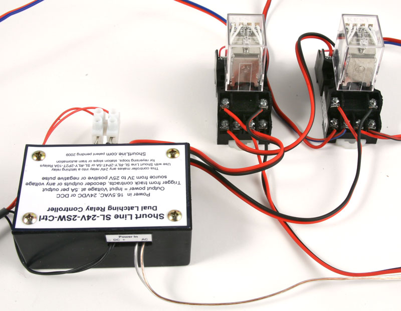
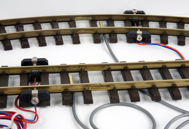
- The setup requires a main track (could be a simple oval of track) and a siding for parking one one of the trains. Each of the three sections of track must be isolated (the yellow plastic blocks below provide isolation) and each section of track is connected to the relays as shown below. Two SL-TC-17100-nt Track Contacts are placed on the parking tracks where you want the trains to stop and the SL-24V-2SW-Ctrl is connected to a power source (the 18VAC power is used on one of the train power packs below in this example)
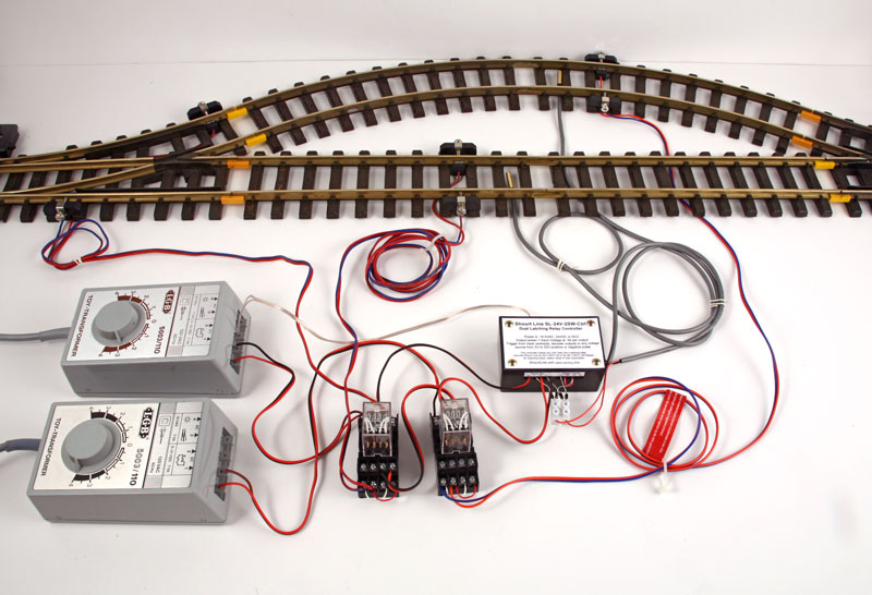
- Here is a schematic of the hookup. Note the 4 diodes indicated and the direction of the arrows. These diodes are included with the two SL-TC-17100-nt Track Contacts and the diodes have a stripe on one end that indicates the direction of the arrows in the schematic which is also the direction of current flow. Be sure to place the diodes as shown. Click here or the drawing to download or open a PDF version.

- This close up photo shows how the diodes are connected to the SL-23V-2SW-Ctrl and the SL-TC-17100-nt Track Contacts using a SL-TS-17A-12 Euro Style 12 Position Terminal Strip cut to 3 terminals.
- This close up shows one side of the relay wiring
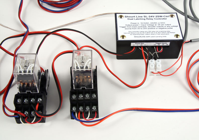
- This close up shows the relay hookup on the other side as well as the power connection and how the track contacts connect to the DC negative terminal for ground return.
- This close up shows the track power connections and placement of the track contacts just prior to putting them under the track ties (optional)
- Click here for a much larger photo of the wiring photo shown below.
- Run Your Trains - Place locos with loco magnets on the track over the track contacts in opposite directions and apply power. One of the power packs will start running one of the locos at the speed and direction you set. When this loco returns to its starting position over a track contact, the loco will stop and the other loco will start to run at the speed and direction you set.
- Use electrical switch tracks (Optional) This example uses a manual switch track with spring return but a power switch track could be used as shown in the next section. In this way the switch tracks will be set to the correct siding as the loco leaves its parking track. In this way you can run trains in the same direction. The trains will continue to run alternately until you shut off the power or set one of the throttles to zero.
- Stop On DC (Optional) By using locos with Massoth DCC decoders, which have stop-on-dc, your can use the locos' deceleration and acceleration momentum rates (set by CV value) to gradually slow your locos to a stop and gradually accelerate to your preset speed and direction if DCC power is switched to and from DC power. In addition the lights will remain on as well as the smoke generator and sound units will have full power for breaking and standing sounds. This requires a slight modification to the wiring diagram so in stead of removing power to the track to stop the train, the track receives DC (rectified DCC) power. Click here to print or view this wiring diagram.
- Keep Automating - Create automated trolley lines, reversing loops, full train layout automations or your own designs in a similar way. Please contact us for these and other application notes and share your ideas with us so we can share them with others.
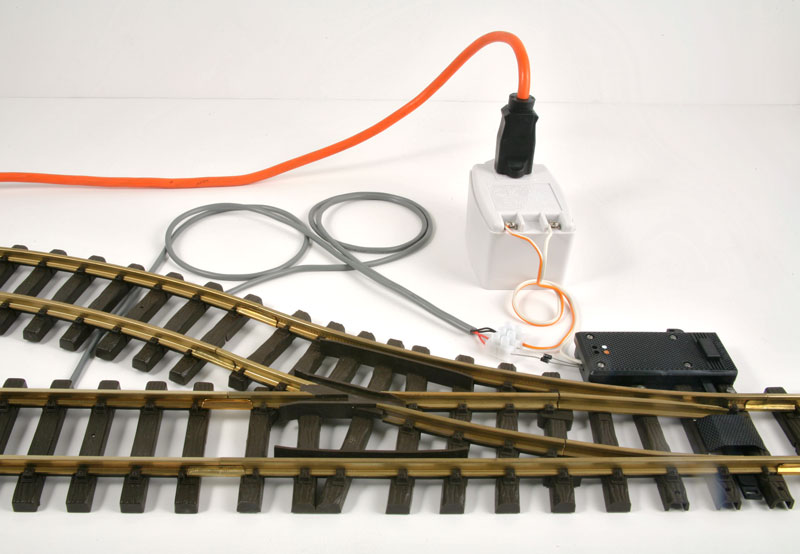
To Operate the previous example using electric switch tracks you can automate your electrical switch and signal motors directly from the SL-TC-17100-nt Track Contacts by following these directions (or click here for more methods of switch control)
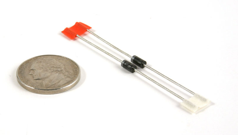
- Each track contact comes with two diodes for use with AC power to drive EPL motors in either direction.
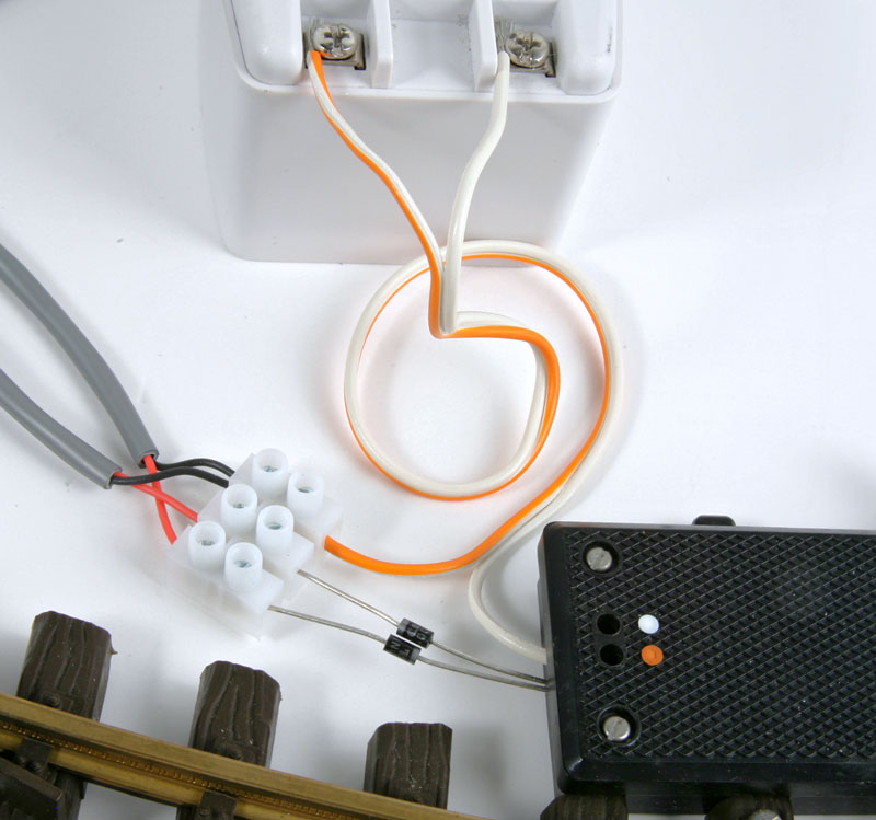
- Connect two track contacts to open and close a switch motor as the train passes each contact. Power is provides by a Shourt Line SL-PS-16AC40 16 VAC 40 Watt Transformer and connected to one pole of the motor (white wire below) and each wire of the track contact (black wires below) via a the optional terminal strip to the orange wire running to the other output of the transformer.
- This close up view shows how easy it is to hook-up the track contacts to an EPL switch motor using the diodes two diodes provided with teach track contact. The optional terminal strip can be used or the contact wires can be soldered directly to the diodes and covered with heat shrink tubing.
- As a loco magnet passes each contact, the switch motor opens and closes to provide automation for your layout.
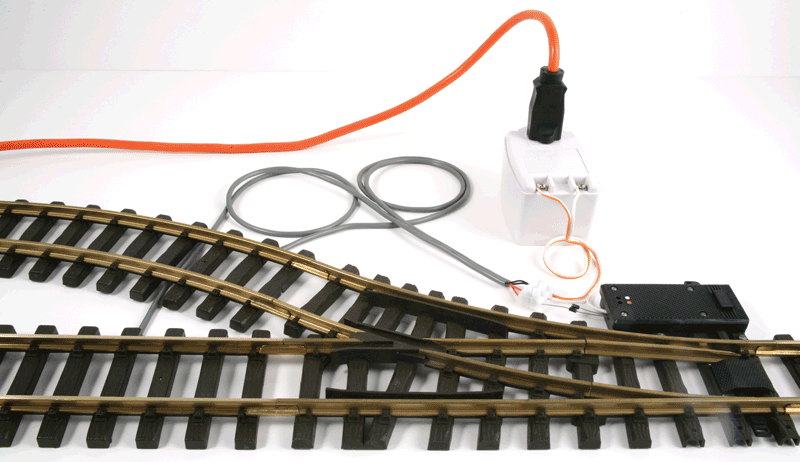
As a loco magnet passes each contact, the switch motor opens and closes to provide automation. Note: remember to connect both switch motors in parallel for the previous two train controller example.
Run your trains!
Track, transformer and train not included WITH THIS ITEM.
Connection Schematic for power switch tracks from switch contacts:
Use a 16 Volt AC power source when powering your track and signal motors directly from the track contacts. Use the included diodes to wire as to power and loads as shown below and in the pictures above. Note each diodes polarity.
For indoor or outdoor use. (See our product page for the optional terminal block).
Questions? Email info@ShourtLine.com by clicking here
Thanks for looking - Shourt Line by Soft Works Ltd.
copyright 2008 Shourt Line - Soft Works Ltd. all rights reserved
How to Order